Examples

Ratchet Wheel
The design above allowed us to experiment with the polar array feature. This allowed us to quickly create a full jagged circle and equally spaced holes to make the drafting process more efficient Orthographic Projections
Control Block
Now we have moved to orthographic projections, which are three sided views that show all sides of an object. With these types of drawings, we can more accurately represent more complex shapes and start to get a 3-D feel for the object. Isometric Projections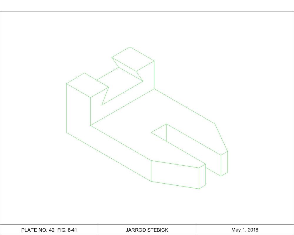
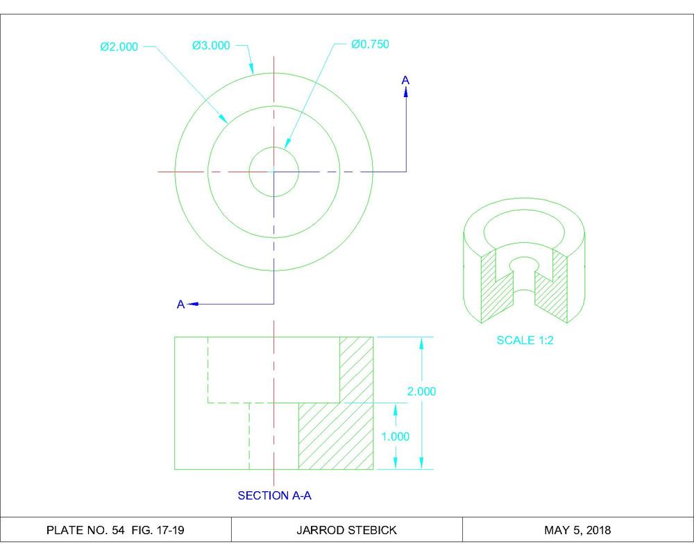
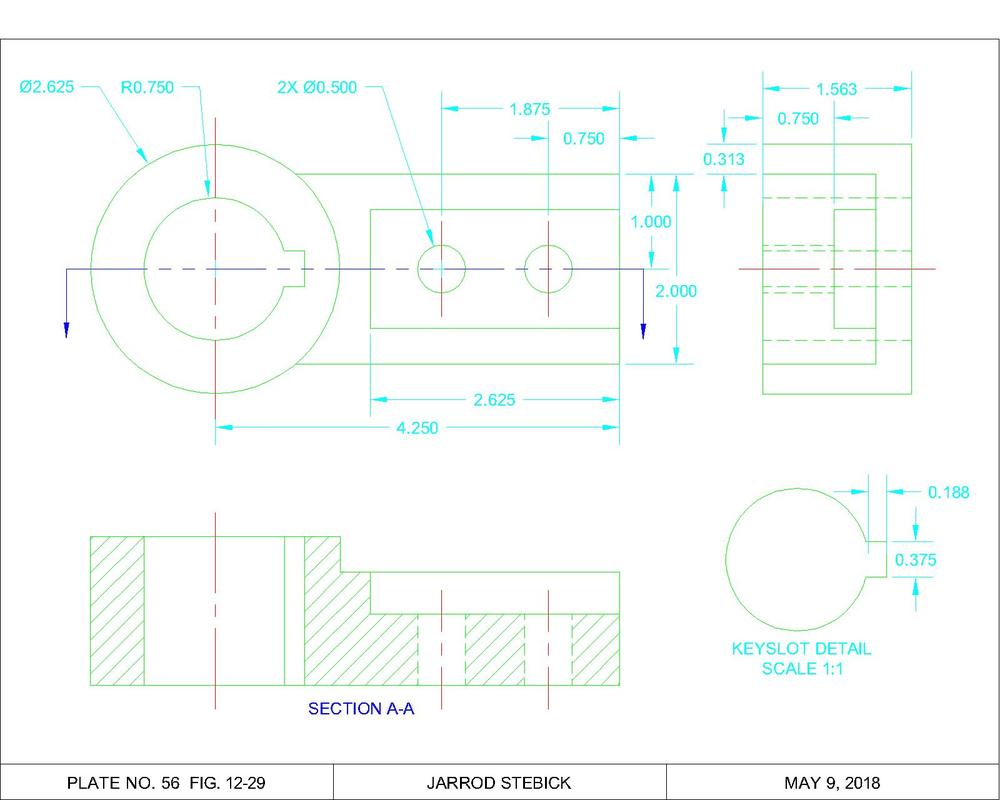
Section Drawings
|

Gasket
The gasket drawn above was one of the final mechanical drawings we completed. A drawing that may have originally taken one or two periods to complete by hand was now completed in minutes with CAD. Orthographic projections are multi-view drawings of an object in order to show all features. This typically includes a top, front, and ride side view to show depth, length, and height respectively. However, for simpler or symmetrical objects less views can be shown

Packing Gland
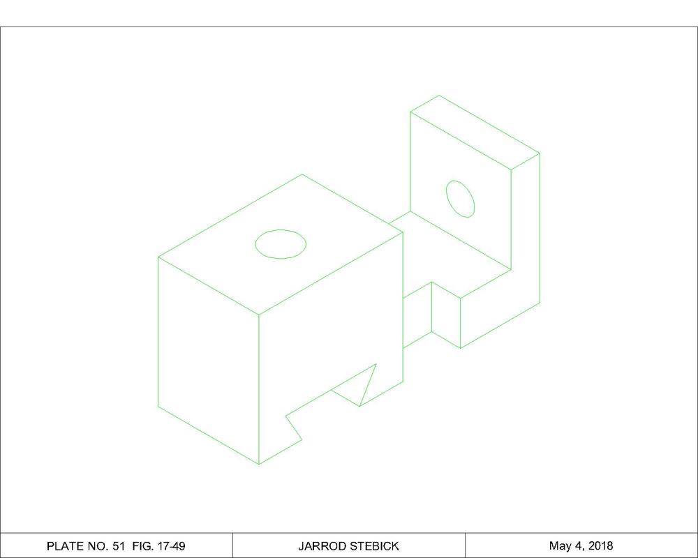
The orthographic projection shown above was dimensioned correctly to show all the necessary specifications for the object. The overall dimensions were placed between the views and the dimensions specific to the views placed in their respective areas. Isometric projections show a false 3-D of an object to help the drafts person or manufacturer gain a better understanding of the part they are making. Done with AutoCAD, this view uses a separate grid snap at 30 and 60 degree angles to give the false
3-D look 
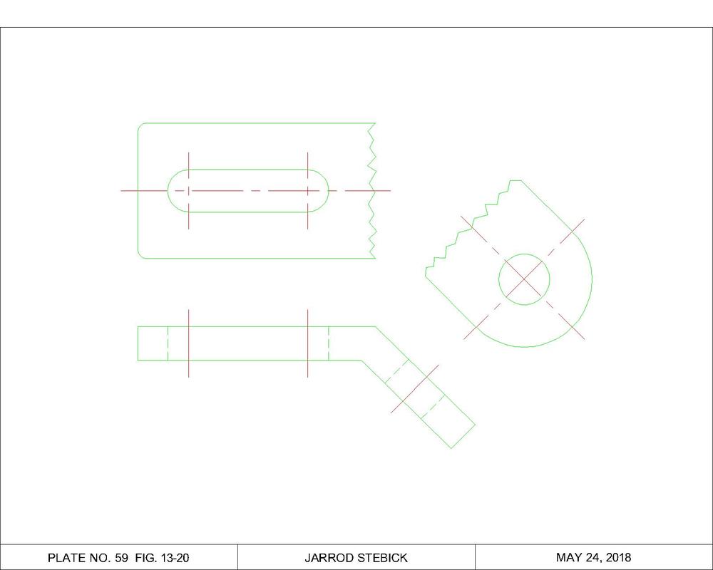
Auxiliary DrawingsAuxiliary drawings, such as the drawing shown below, show the part of an object whose true size cannot be shown from a standard orthographic projection or 90 degree angle. Instead this object has a view perpendicular to the surface which is projected. This allows the reader to see the true size and shape of the object in order to correctly make the object.
|
